Notice: This Wiki is now read only and edits are no longer possible. Please see: https://gitlab.eclipse.org/eclipsefdn/helpdesk/-/wikis/Wiki-shutdown-plan for the plan.
JWT Tutorial Guards
Datatypes and guards are a very important part of BPM since they allow to control the execution semantics of a workflow and the connection to the data handling in the runtime engine. This tutorial covers creating simple datatypes and guards that can be tested with the AgilPro simulator. The example builds upon the workflow described in the Adding technical data tutorial.
Creating a simple data type
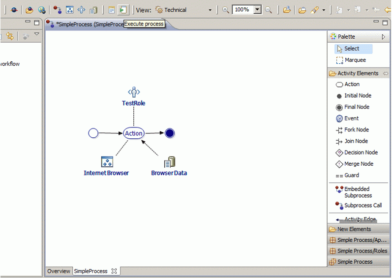
We start with this workflow:
Assume that somebody wants to have a decision whether to go to the internet or not. Then you will need some additional applications, data and control nodes. First we add a new application called “Generic GUI” with the class eu.emundo.agilpro.fw.fe.intf.GenericUi to execute.
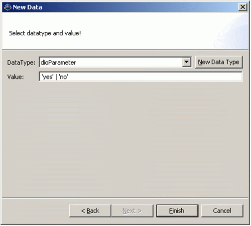
Then we create some data called “Decision” with a new data type called “dioParameter” and the decision possibilites ‘yes’ and ‘no’.
Creating guards
There is an easy way to create guards so that the conditions can be tested in the AgilPro Simulator (see the AgilPro Tutorial) without any additional effort. To use this feature you always have to create two elements in your model first (what you already did if you followed the steps described above).
- An application using 'eu.emundo.agilpro.fw.fe.intf.GenericUi' as Java Class, which offers a generic user interface that lets you choose the values of your guard conditions in drop down menus.
- A datatype named 'dioParameter'
Create data elements for each property you want to use in a guard. As datatype always choose the dioParameter. The value field of the dioParameter has to be filled with all possible values, that should be available for selection, in the following way: 'value1' | 'value2' etc. (remark: the ' ' are really needed). For this example create a data Element “Decision” and use the dioParameter as datatype.
Now you are able to create the guards for each activity edge. Guards consist of a textual description and a short description. The textual description is shown if the workflow editor switches to the business view. It is used to simplify the condition or to put it into an expression in natural language and has no influence on the interpretation of the condition.
The short description represents the technical expression of the condition. It has to satisfy several requirements regarding the syntax. To construct the expression all letters, brackets and the common operators ==, <=, >=, !, &&, || are allowed to be used. To create a correct guard using data objects, you have to reference to your data objects in a special way. Assumed you want to use your data element named “Decision”, you can access it in the short description by writing Decision.Decision. The values you have specified for this data element can now be used in the boolean expression for your condition, e.g. a simple short description of a guard could be:
Condition.Condition == yes
(remark: the ' ' you had to use in the specification of the values for the data element have to be omitted now)
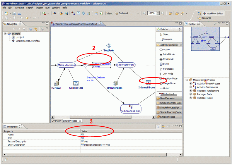
The following screenshot tries to describe the creation of guards in one window: First you select the guard from the palette, drag and drop it onto the line (second) and specify the textual description and the short description in the properties view (third).
The guard specifications become more complicated if you use the operators && or || in the short description of your guard. Now there are several guard specifications ordered in the hierarchy you forced by your boolean expression. The simulator evaluates only the bottom guard specifications and connects them with the adequate boolean operator. The guard specifications that collect only other specifications are not part of the evaluation by the simulator.
After you’ve added the guards Decision.Decision == yes and Decision.Decision == no to the activity edges as well as the additional application and data, you might have the following process. Note that the decision has now an InOut edge, meaning that it is as well an input to the action “Make decision” as an output. You can achieve this by drawing the line once from the action to the data and once from the data to the action.
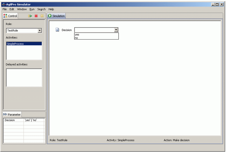
Executing this in the AgilPro Simulator you can see a generic GUI that asks you for “yes” or “no” (okay, quite simple, but you can of course think of much more complicated examples):
If you select “yes” then you can see the browser, otherwise not.


