Notice: This Wiki is now read only and edits are no longer possible. Please see: https://gitlab.eclipse.org/eclipsefdn/helpdesk/-/wikis/Wiki-shutdown-plan for the plan.
ICE Embedded Visualizations
The capabilities in this document are brand new, and while we assert that they work, that may not be the case on all systems for all users. Problems should be reported directly to the ICE team by sending an email to the project list, ice-dev <at> eclipse.org, or following the instructions to report bugs on our Bugzilla.
Introduction
This document describes the embedded visualization capabilities available in ICE. Embedded visualizations in ICE aim to provide users with immediate yet simple visualization of simulation input and output well within the simulation workflow. In other words, simulation input and output can be visually verified or validated without leaving the associated Model Builder or Job Launcher in ICE. For more advanced or complex visualization tasks in ICE, please see the document on Visualizing Output with ICE.
Resources and Resource Pages
ICE Items may include any number of Resources, which may include any type of file like meshes, pictures, shell scripts, .csv files, or even plain text files. For example, a Model Builder, which is used in ICE to configure simulation input, may at some point include a plain text input file as well as associated data files or meshes. Likewise, a Job Launcher, which actually launches the simulation, may produce any type of output data, which may also include .csv files, binary files, or even more mesh files.
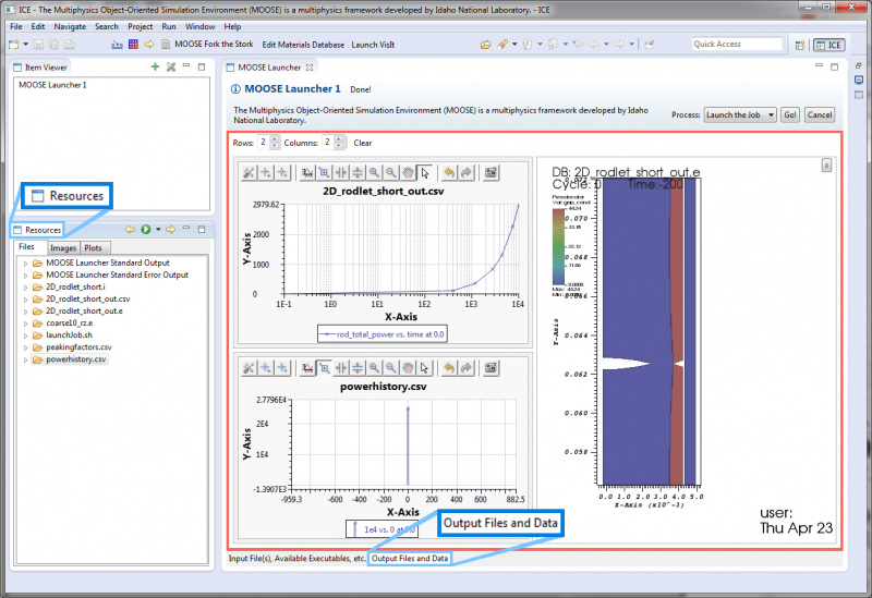
Before proceeding, you should familiarize yourself with the Resources View (highlighted in blue on the left) and the idea of a Resource Page (highlighted in red, while its tab is highlighted at the bottom) as shown in the image below.
The Resources View
Some Items in ICE store references to these resources for easy access to the user. In these cases, the resources are presented to the user in the Resources View, which is part of the default ICE perspective.
The Resource View is actually a tree, where each resource has its own node. If you expand a resource node, it will reveal the underlying file's path along with its date of last modification.
Resource Pages
If an ICE Item includes resources, it will have a designated tab for showing those resources.
- For Model Builders, this tab could be named anything. For instance, in the MOOSE Model Builder, the tab for viewing resources is called Mesh.
- For Job Launchers, this tab will be named Output Files and Data.
Click on the tab to open it and view the Item's Resource Page. Each Resource Page is capable of showing plain text files or embedded visualizations based on the selected resource's file type.
Viewing a Resource
To open a resource, go to the Resources View and double-click its item in the list of available resources. The way ICE handles this selected resource depends on the following:
- If the file can be opened using one of the visualization services, it will be added to the active Resource Page.
- If the file can be opened using a plain text editor, it will be opened in a new Text Editor in ICE.
- If the file cannot be opened, the Resource Page will attempt to render it through a browser widget. This handles some basic files like certain image types.
- If the file cannot be opened in the browser, the browser will prompt you to save the file. In this case, you can either save it, or cancel and open the existing file at the location specified in the Resources View.
This document will not discuss the latter three situations any further. The next sections will describe the embedded visualizations from the first scenario.
Controlling Embedded Visualizations
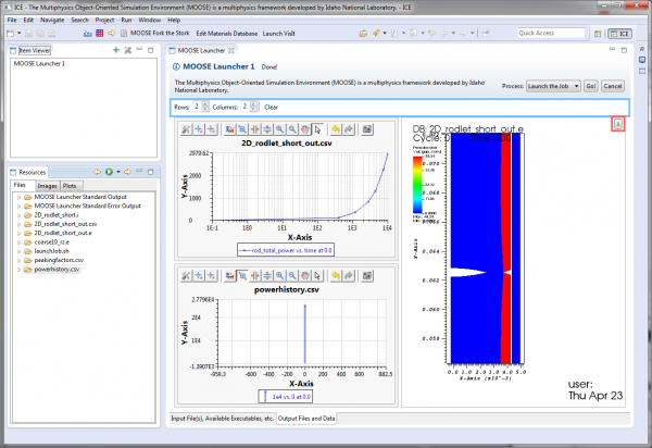
Each Resource Page can display a number of embedded visualizations at any time. Selected plots are displayed in a grid defined by the Rows and Columns widgets in the toolbar (highlighted in blue in the image below) near the top of the page, although embedded plots will take up as much space as they can. The default grid is two by two, although the number of rows and columns can be changed at any time.
Adding Plots to the Grid
To add a new plot to the grid, simply go to the Resources View and double-click the desired file that can be rendered by one of ICE's visualization services. Note that the order in which plots appear in the grid depend on the order in which they are added to the grid, with the grid moving left-to-right, top-to-bottom.
Removing Plots from the Grid
To remove an individual plot, you have two choices:
- You can hover the mouse cursor over the plot, then click the "X" button that appears (highlighted in red in the image above).
- You can right-click somewhere inside the plot, then click Remove.
You can also remove all plots at once by clicking the Clear button in the Resource Page's toolbar. This is located next to the widgets for controlling the size of the grid.
Right-click Menus
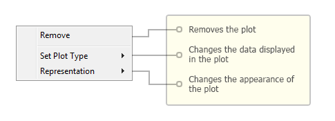
Every plot drawn inside the Resource Page includes a right-click menu that provides the following basic options:
- Remove - Removes the plot from the Resource Page
- Set Plot Type - Provides nested sub-menus that let you set what is displayed in the plot.
The contents of the Set Plot Type sub-menu depends on both the file and the visualization service used to plot it. Generally, you first choose the plot category from the first sub-menu and then a type from the category sub-menu.
Additional menu choices may be available depending on the visualization service that provides the plot.
Visualization Services
VisIt
Prerequisites
To use the embedded visualization service for VisIt, ICE requires a local installation of VisIt (minimum version 2.8.2, maximum version 2.9.2) developed by Lawrence Livermore National Laboratory.
Preferences
Getting to the Preferences
Using the VisIt visualization service for viewing complex 2D or 3D mesh data requires little initial configuration. Assuming the VisIt prerequisite is installed, use the the main menu bar at the top of the window and navigate to:
Window > Preferences
In the Preferences dialog, navigate to:
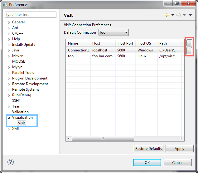
Visualization > VisIt (highlighted in blue in the image below)
Adding Connections
You will need to press the "+" button (highlighted above in red) to the right of the table to add a new entry. Fill out the new row in the table. Generally speaking, the default values are fine, but the Path will need to be updated to point to the folder containing your VisIt executable.
For example, on Windows, if assuming a username of "username", and VisIt was installed in the default location, the path will be:
C:\Users\username\AppData\Local\Programs\LLNL\VisIt 2.9.2.
On Linux, the path will be based on where you extracted the visit2_9_2.linux-x86 folder, ending with ~/visit2_9_2.linux-x86_64/bin. If you unzipped it to the desktop, it will be:
/home/username/Desktop/visit2_9_2.linux-x86_64/bin
On Mac OS, the path will be based on the location you put the Visit application. If placed in the Applications folder, it will be
/Applications
Setting the Default Connection
Currently, only one connection to VisIt can be used at a time. If you only have one configured connection, it is automatically selected as the default. However, if you have multiple configured connections, you will need to set the default connection by choosing from the drop down above the table.
Removing Connections
To remove a connection, click on any cell in its row in the table, then click the "-" button (highlighted above in red) on the right of the table. You can select multiple connections by holding CTRL while you click them, then clicking the "-" button.
Applying the Connection Preferences
When you have finished updating your connection configurations for VisIt, you can click OK to apply the changes and close the Preferences dialog. Alternatively, you can apply the changes immediately by clicking Apply. It is then safe to close the Preferences dialog in any valid way, e.g., by clicking the dialog's close button or by clicking Cancel.
Opening a VisIt Plot
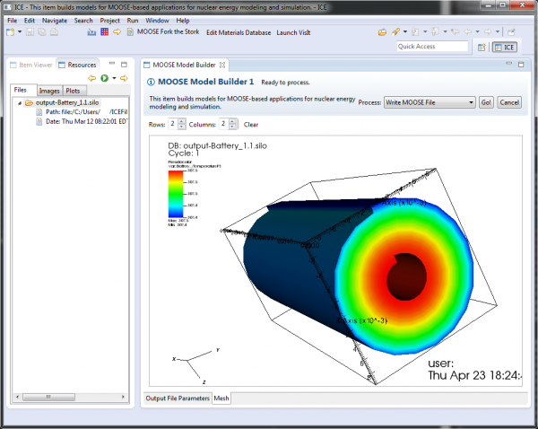
The Resources View will pass any ICE resources pointing to .e (Exodus) or .silo files to the VisIt Visualization Service. If the visualization service is configured and running and if the file is valid, then the Resource Page will open a view of the resource powered by the default VisIt connection, as in the image of a battery mesh SILO file below.
An example VisIt plot embedded in a Model Builder can be seen in the image below.
The embedded VisIt view can be rotated by clicking and dragging and zoomed in and out with the mouse wheel.
Right-click Menu
The image below shows the context menu available when right-clicking somewhere inside the VisIt view.
The plot types available in the context menu depend on the data available in the VisIt-compatible file. In the case of this SILO file, the only plot categories are Meshes and Scalars.
The context menu also includes the ability to change how the VisIt plot is rendered. The representations available depend on the current plot type. A full list of supported "representations" is listed below for each plot category.
- Materials
- Boundary (default)
- FilledBoundary
- Meshes
- Mesh (default)
- Scalars
- Pseudocolor (default)
- Contour
- Volume
- Vectors
- Vector (default)

