Notice: This Wiki is now read only and edits are no longer possible. Please see: https://gitlab.eclipse.org/eclipsefdn/helpdesk/-/wikis/Wiki-shutdown-plan for the plan.
Tutorial: Raspberry Pi GPIO with OSGi Services
Contents
Introduction
This tutorial shows how to use OSGi Services to access the Raspberry Pi GPIO. The use of OSGi Services to use GPIO provides several important advantages:
- The OSGi Service Interface provides a simple and clear yet flexible software abstraction
- Clear Contract Between Service Producer and Service Consumer
- Loose Coupling and High Cohesion
- Flexible yet Simple Abstractions
- OSGi Services provides technical advantages
- Service Dynamics - Services come and go, applications can be notified and adjust
- Service Versioning - Services evolve over time
- Variety of Injection Frameworks - e.g. Declarative Services, Blueprint/Spring
- Network Services - ECF Remote Services
- Service-Level Security
GPIO Pin Output
Each GPIO digital pins have two modes: output and input. For output, each pin can be in either the 'HIGH' state, or the 'LOW' state, and the control of the pin state is what we would like to manipulate to give our application behavior. After connecting a single LED, changing the output on a given pin to HIGH will turn the LED on, while setting to low will turn it off. See this page for a description of how to setup such an LED.
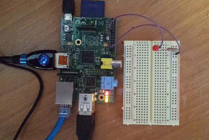
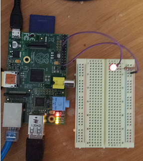
We would like to use OSGi services to simplify software access to devices connected to the GPIO digital pins. Here's a picture of a Raspberry Pi setup with an LED connected to GPIO digital output pin 0, as per the instructions here. This is the setup that I use to test the services described below
For OSGi services, we start by creating a service interface declaring the methods for accessing a single GPIO pin. Here is the IGPIOPinOutput service interface:
public interface IGPIOPinOutput extends IGPIOPin {

	public boolean getState();

	public void setState(boolean value);

...

}
For this tutorial, we will be interested only in the getState and setState methods from this service interfaces. Note that we can create as many instances of this service interface as desired, but are limited by the GPIO device itself, which has two rows of 10 pins for a total of 20 physical pins.
Since the implementation of this interface already exists, all we need to do use the IGPIOPinOutput service is to write our application code so that OSGi service instances of this type are accessed for the pins we are interested in manipulating.
To find and use an instance of IGPIOPinOutput we can use one of several OSGi mechanisms: 1) Declarative Services; 2) ServiceTracker; 3) BundleContext. For this tutorial, we will use a very simple ServiceTracker. The full code for this example can be located in the registerTracker method of the AbstractPinManager class. The important fragments from this example are the implementation of the addingService method, which is executed when instances of IGPIOPinOutput are registered in the OSGi service registry
public IGPIOPinOutput addingService(ServiceReference<IGPIOPinOutput> reference) {
	IGPIOPinOutput pin = fBundleContext.getService(reference);
        ...
	System.out.println("Adding GPIO Pin Output service. id="+ reference.getProperty(IGPIOPinOutput.PIN_ID_PROP));
        System.out.println("  current pin state is "+ (pin.getState() ? "HIGH" : "LOW"));
	System.out.println("  setting state to HIGH");
	pin.setState(true);
	return pin;
}
When the IGPIOPinService is added, the service.setState(true) method is called, which will set the state of the pin to HIGH, turning on the LED connected to that pin.
As well, we will implement removedService which is executed when instances of IGPIOPinOutput are unregistered.
public void removedService(ServiceReference<IGPIOPinOutput> reference,
                           IGPIOPinOutput service) {
    System.out.println("Removing GPIO Pin service. id="+reference.getProperty(IGPIOPinOutput.PIN_ID_PROP));
    System.out.println("  setting state to LOW");
    service.setState(false);
}
When the service is removed, the service.setState(false) is called, which will set the state of pin 0 to LOW, turning off the LED connected to that pin.
When this test bundle is run on a Raspberry Pi (using Java8+Equinox 4.4), this appears on the OSGi console:
osgi> start 3
Adding GPIO Pin Output service.   id=0
  current pin state is LOW
  setting state to HIGH
the LED lights up
If we then stop this test bundle, this appears on the OSGi console
osgi> stop 3
Removing GPIO Pin service. id=0
  setting state to LOW
and the LED goes out.
Here is a short video showing the running of this test code by using the Apache Webconsole. Thanks to ECF committer Wim Jongman for creating the video.
GPIO Input
In addition to controlling devices that are connected to one or more GPIO pins, it's also possible to receive asynchronous notifications of inputs to digital pins. To do this with OSGi services we will use a very useful OSGi service pattern called the whiteboard pattern. The whiteboard pattern is described in links given under Related Articles below.
For the whiteboard pattern we need another service interface, called IGPIOPinInputListener
public interface IGPIOPinInputListener {

	void handleInputEvent(GPIOPinInputEvent event);

}
and the associated GPIOPinInputEvent
public class GPIOPinInputEvent extends AbstractGPIOPinEvent implements
		Serializable {

	private static final long serialVersionUID = -6103636181685626657L;

	private final boolean state;

	public GPIOPinInputEvent(int pinId, boolean state) {
		super(pinId);
		this.state = state;
	}

	public boolean getState() {
		return state;
	}

	@Override
	public String toString() {
		return "GPIOPinInputEvent [getPinId()=" + getPinId() + ", state="
				+ state + "]";
	}

}
With the whiteboard pattern, instead of clients looking up/retrieving services (as with IGPIOPinOutput and the ServiceTracker given above), what's necessary is that the IGPIOPinInputListener be implemented and then an instance registered in the OSGi Service registry. For example, here's a very simple class that implements IGPIOPinInputListener
class TestGPIOPinInputListener implements IGPIOPinInputListener {
    @Override
    public void handleInputEvent(GPIOPinInputEvent event) {
        System.out.println("TestGPIOPinInputListener.handleInputEvent(event="+event+")");
    }
}
and then we create an instance of this class, create some service properties and register this instance via the OSGi BundleContext (context):
// Create properties
Hashtable props = IGPIOPin.Util.createInputListenerProps(IGPIOPin.DEFAULT_INPUT_PIN);
// Create and register listener using context and props created above
context.registerService(IGPIOPinInputListener.class, new TestGPIOPinInputListener(), props);
This listener is then notified and produces output when the DEFAULT_INPUT_PIN changes it's state:
TestGPIOPinInputListener.handleInputEvent(event=GPIOPinInputEvent [getPinId()=2, state=false])
All of the code above is provided in the ECF RaspberryPi github repository. The service interfaces above (IGPIOPinOutput and IGPIOPinInputListener and event classes) are available in the bundles/org.eclipse.ecf.raspberrypi.gpio project.
Also available is a complete working implementation of this service API based upon/using Pi4j. This implementation is in the bundles/org.eclipse.ecf.raspberrypi.gpio.pi4j project.
Remote Control for GPIO Pins
See the OSGi Remote Services for Raspberry Pi GPIO tutorial.
Related Articles
Listeners Considered Harmful: The 'Whiteboard Pattern'
OSGi Remote Services for Raspberry Pi GPIO
Getting Started with ECF's OSGi Remote Services Implementation


