Notice: This Wiki is now read only and edits are no longer possible. Please see: https://gitlab.eclipse.org/eclipsefdn/helpdesk/-/wikis/Wiki-shutdown-plan for the plan.
EMF Compare/Specifications/GraphicalComparison
THIS PAGE IS ARCHIVED. IT IS PROBABLY OUTDATED AND WILL NOT BE UPDATED
Contents
Evolution Specification: Graphical Comparison
Current status is ARCHIVED
Preamble
Summary: This feature is about all topics around the comparison of graphical objects.
Links to the Bugzilla tickets which are related to the change:
- Bug 400816 - Phantom display of removed graphical items
- Bug 401526 - Enhance markers of graphical comparison
Links to messages forum:
Introduction
PENDING This section should contain a summary of the proposed evolution, including why it is needed. Ideally it should be self-contained so that non-developers can get a quick overview of the evolution without reading the detailed specification.
Detailed Specification
User Interface
The aim is to be the most consistent with the look of the "semantic" comparison (tree).
- The same mechanism of color management will be used (standard behavior of eclipse compare):
- One color for local changes (grey by default). The end-user will see these new changes on the left side.
- One color for remote changes (blue by default). The end-user will see these new changes on the right side.
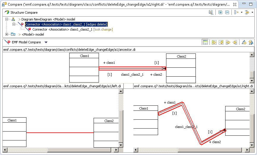
- One color for conflicting changes (red by default). The end-user will see these changes on the both sides and he will base on the ancestor one to understand them better.
- To put in relief the graphical differences, some decorators should be used:
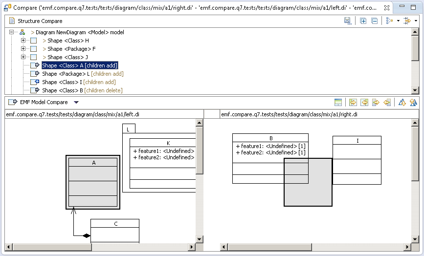
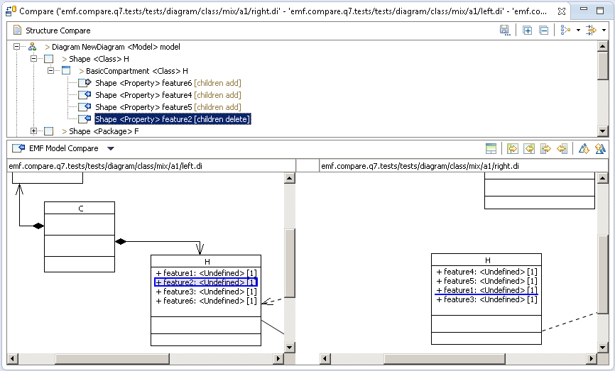
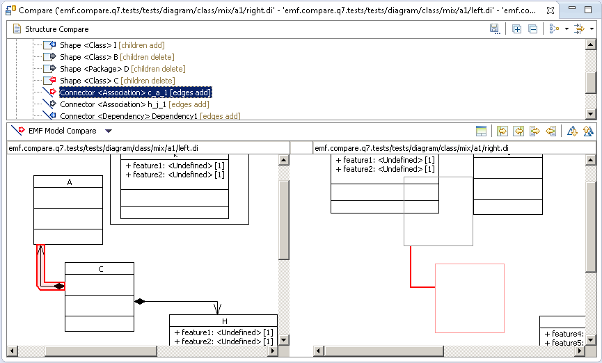
- On one hand, to focus on the impacted objects, identifying them with markers. These markers will be simple transparent rectangles which will be set down above the concerned objects and they will be lightly larger.
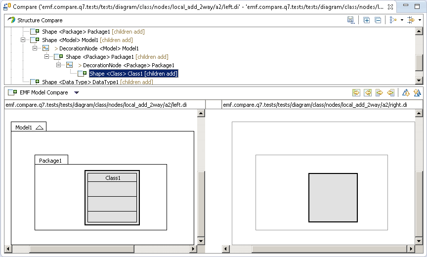
- On the other hand, through phantoms (place-holders), to locate either the place where objects were deleted or the target location where objects should be added after merging.
- The color of the concerned decorators will be highlighted on selection of the difference.
Not to overload the diagrams to compare and to ease the understanding of each difference, only the decorators concerned by the selected change will appear.
About phantoms (place-holders):
- To ease their readability, in some cases, their context will have to be displayed:
- If they are nested in an other phantom (e.g. due to a delete of the parent object), this last contextual one will be displayed at the same time as the main phantom concerned by the current selected change.
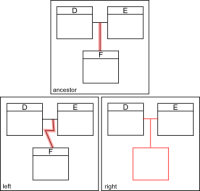
- If they are edges connected to deleted nodes or edges, these last contextual ones will be displayed at the same time as the main edge phantom.
- The color of the contextual phantoms (dependencies) will not be highlighted.
- They will be drawn as:
- A simple rectangle for nodes, at the same origin location (and size).
- A simple line (with the same bend points) for edges, at the same location.
- A simple line for nodes as element of containment list. For this case, The same LCS computation will be used to locate in the list, at the good index.
- Particular cases: If the location of the contextual phantoms was changed, the new location of the main phantom has to be computed.
- A node place-holder, related to a delete of a node, embedded in a node where the location changed.
- An edge place-holder between nodes where the location changed. In this case, the display of the line will have to be drawn again (it will be a default display, computed by GMF, without potential bend points).
Below, different cases are detailed (see #Non_conflicting_cases and #Conflicting_cases).
Changes computation
- Unit changes:
By default, changes on the GMF notational model will be computed through the EMF Compare generic engine. So, the comparison will provide a high precision level with every unit changes and their required computed differences (see #Required Changes).
- Macroscopic changes:
The unit changes will be encapsulated in macroscopic changes in order to simplify the understanding of these ones. In other words, graphical macroscopic changes are refined by unit changes on GMF notational model (see #Refining Changes). The display of the graphical objects in the user interface, with the comparison decorators, will be triggered from the selection of these macroscopic changes.
The macroscopic changes will be able to define their own and specific requirements to other macroscopic and unit changes (see #Required Changes).
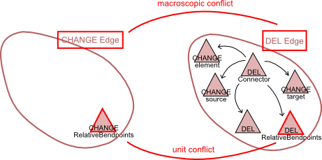
A macroscopic change will be considered as being in conflict if one of its refining changes is in conflict at least (see #Conflicting cases).
Required Changes
- The computation of the required differences from unit graphical changes inherits from the generic behavior:
See [[1]]
- Additional requirements have to be computed from the graphical macroscopic changes:
According to the requirement links between unit differences, requirements will have to be computed between the related macroscopic changes (dependency analysis on these ones).
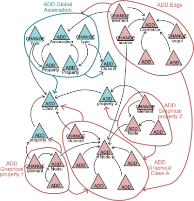
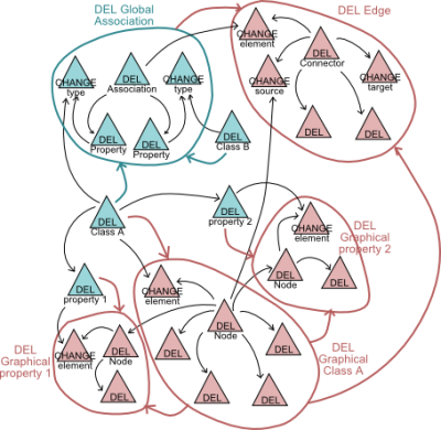
A requirement may exist between a unit difference and a macroscopic change. For example, the delete of a UML Class requires the delete of the "element" reference from the GMF node. So, the delete of the UML Class requires the macroscopic delete of the set of the GMF nodes which compose the related graphical object (containing the impacted GMF node). If this link did not exist, the graphical object would be "broken" without this "element" reference.
See #Merge of macroscopic changes.
Refining Changes
Macroscopic changes for diagram comparison are defined to group a set of unit differences related to the notational model and to obtain a global vision. So, the macroscopic changes are refined by other unit changes.
| Macroscopic changes |
Kind |
Refined by: |
| Edge Change | ADD |
|
| DELETE |
| |
| CHANGE |
| |
| MOVE |
N/A | |
| Node Change | ADD |
|
| DELETE |
| |
|
CHANGE (coordinates) |
| |
| MOVE |
| |
| Hide Change |
CHANGE |
|
| Show Change |
CHANGE |
|
Merge of macroscopic changes
The merge of graphical macroscopic changes consists in merging the potential required differences then the refining ones.
Each refining difference will merge its required ones before merging itself.
According to the kind of difference and the way of merge, either "requires" or "required by" link will be used to merge the requirements. Remember that the "requires" link is set according to the kind of difference. See [[2]]
To merge the refining differences, the link "refined by" will be used whatever the way of merge.
The move of a GMF notational node may involve a coordinates change of this same node. So, the macroscopic change MOVE will include the unit coordinates change.
Non conflicting cases
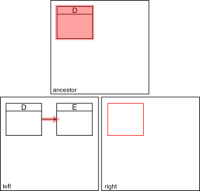
- Locally added elements:
|
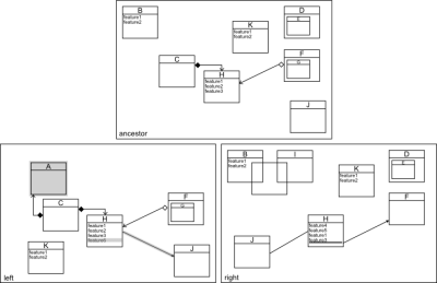
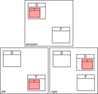
You can see a locally added object on the left side of the comparison viewer. It is identified by a marker in transparent highlighted gray color (default color). On the other side, a phantom with the same color is drawn, as place-holder, in order to locate the place where the related object would be added if the end-user merged from left to right. In this example:
|
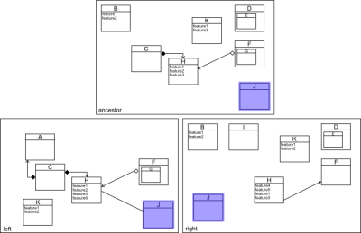
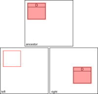
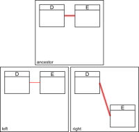
- Locally deleted elements:
|
You can see a locally deleted object on the left side of the comparison viewer. It is represented by a phantom in highlighted gray color (default value), as place-holder. On the other side, the related object is identified by a marker with the same transparent color. On the ancestor version, the origin object is marked too. In this example:
|
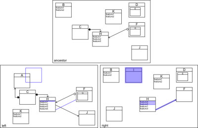
- Remotely added elements:
|
You can see a remotely added object on the right side of the comparison viewer. It is identified by a marker in transparent highlighted blue color (default color). On the other side, a phantom with the same color is drawn, as place-holder, in order to locate the place where the related object would be added if the end-user merged from right to left. In this example:
|
- Remotely deleted elements:
|
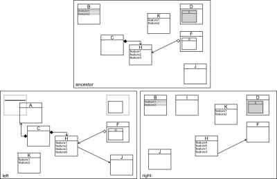
You can see a remotely deleted object on the right side of the comparison viewer. It is represented by a phantom in highlighted blue color (default value), as place-holder. On the other side, the related object is identified by a marker with the same transparent color. On the ancestor version, the origin object is marked too. In this example:
|
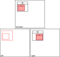
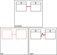
- Local coordinates changes:
|
You can see a local coordinate change on the left side of the comparison viewer. The object concerned by this change is identified by a marker in transparent highlighted gray color (default color). On the other side or the ancestor version, the same object, at the old location, is marked with the same color too. In this example:
|
- Remote coordinates changes:
|
You can see a remote coordinate change on the right side of the comparison viewer. The object concerned by this change is identified by a marker in transparent highlighted blue color (default color). On the other side or the ancestor version, the same object, at the old location, is marked with the same color too. In this example:
|
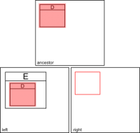
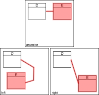
- Local move (and potentially coordinates change):
|
You can see an object moved from a container to another one, on the left side of the comparison viewer. The object concerned by this move is identified by a marker in transparent highlighted gray color (default color). On the other side or the ancestor version, the same object, at the old location, is marked with the same color too. In this example:
|
Conflicting cases
Let's do a combinatorial analysis of the possible changes involving conflicting cases.
This result can be enlarged considering changes which lead to other ones subject to conflict:
- DELETE node leads to DELETE connected edges and children nodes
- DELETE edge leads to DELETE connected edges
- ADD node leads to ADD parent node
- ADD edge leads to ADD connected node and edge
- MOVE node may lead to CHANGE node and connected edges
Conflicts
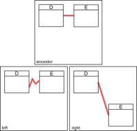
A conflict is created when a change has been made both on left and right side, on the same element.
A macroscopic change will be considered as being in conflict if one of its refining changes is in conflict at least.
The cases of conflicts are (a change from one side <-> an other change from the other one):
- ADD node ↔ DELETE parent node
- ADD edge ↔ DELETE connected edges
- ADD edge ↔ DELETE connected nodes
- DELETE node ↔ CHANGE node
- DELETE node ↔ MOVE node
- DELETE edge ↔ CHANGE edge
- CHANGE node ↔ CHANGE node
- CHANGE edge ↔ CHANGE edge
- MOVE node ↔ DELETE node
- MOVE node ↔ MOVE node
In a general way, a graphical difference (on the GMF notational model) may be related to 0 or 1 semantic one (on the business model). So, a graphical conflict can be related to 0 or 1 semantic one.
For example, the change of the coordinates of a graphical object, in local, may be in conflict with an other change of these coordinates on the same object, in remote. However, no conflict (no difference too) exists at the related semantic objects level.
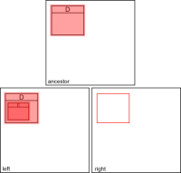
The add of a graphical object (with its semantic one) in a container, on one hand, and the delete of this container (and its semantic one), on the other hand, involves conflicts on the both levels. If the delete concerned only the graphical object, then the conflicts would be only on the graphical level.
Also, a semantic conflict may involve no graphical conflict (e.g. on the name of an object because the change detection is not detected anymore on the graphical level).
The conflicting markers will be visible only for graphical conflicts, on each selection of graphical macroscopic change.
Pseudo conflicts
A pseudo conflict may happen when exactly the same change has been made on both side.
- ADD node ↔ ADD node
- ADD edge ↔ ADD edge
- DELETE node ↔ DELETE node
- DELETE edge ↔ DELETE edge
- CHANGE node ↔ CHANGE node (at the same location)
- CHANGE edge ↔ CHANGE edge (exactly same changes)
- MOVE node ↔ MOVE node (at the same location)
The add of a node/edge on the right and left side may involve a pseudo conflict only if these added elements own the same identifier (in case of manual handling of the XMI source or using of computed functional identifiers).
Some results
Possible enhancements
- In the same way for the detection of coordinates changes, the changes on the size of graphical objects could be encapsulated in a macroscopic change.
- Macroscopic changes for "non semantic" graphical objects.
Backward Compatibility and Migration Paths
PENDING Every one of the sections below should be present. Even if there is no corresponding change (for example no API change), it should exist to mention explicitly "This evolution does not change any API."
Metamodel Changes
PENDING Document any change to the Viewpoint metamodel. If they require a migration operation, mention it and describe the general idea of how migration process. If any information can be lost during the migration, mention it clearly. If validation rules must be added/modified, mention it also.
API Changes
PENDING List every API addition, removal and deprecation. For each removal and deprecation, indicate the migration path for existing code.
User Interface Changes
PENDING List every user-visible change in the interface. Here "user" includes not only end-users but also developpers.
Documentation Changes
PENDING List every documentation needing an update here, starting by the New and Noteworthy documentation.
Tests and Non-regression strategy
PENDING This part of the document should describe the strategy to use to correctly test the evolution and guarantee the non-regression.
Implementation choices and tradeoffs
PENDING Any important tradeoff or choice made during the implementation should be referenced here with pros/cons leading to the final decision.

